
 Need p35C DS3 Vcore/Vdroop mod (ISL6327)
|
Need p35C DS3 Vcore/Vdroop mod (ISL6327)
| |||||||||
 |
 |
| | Thread Tools |
 17th July 2007, 12:02
| #1 |
|
Posts: n/a
| Hi everyone I am desperately searching for a vcore and vdroop mod for the p35C-DS3. The lay out is not the same as the p35-ds3r as in the guide of VR-zone.. This is from the vr-zone guide (DS3R):  And this the lay out from the P35C-Ds3:  The chip on both boards is the same, the ISL6327 This is the pin layout of the chip:  Thnx in advance! Need it really hard!  Last edited by El Snorro : 17th July 2007 at 12:27. |
|
17th July 2007, 21:47
| #2 |
|
Posts: n/a
| Found the vcore mod point, soldered a 50k Vr on it and the vcore mod works  :clap: :clap: :clap: :clap: :clap: :clap:  Ni I only need the vdroop. Anyone have tips? Thnx in advance!! |
|
17th July 2007, 22:17
| #3 |
| Madshrimp  Join Date: May 2002 Location: 7090/Belgium
Posts: 79,021
 | you're quick  my vmodding days have been over for quite some time my vmodding days have been over for quite some time
__________________  |

|
|
17th July 2007, 23:09
| #4 |
| [M] Reviewer Join Date: Nov 2004 Location: Waregem
Posts: 6,466
 | Normally, the soldering points should be the same. Follow the leads from the little chips to the power regulator on the p35-ds3 and see what leg they're attached to. Then do follow the pin from the power regulator on the p35c to the little chips and you should end up with the vdroop mod. Before you mod, check this reasoning first by doing the same for the vcore mod!! |
|
|
|
18th July 2007, 18:49
| #5 | |
|
Posts: n/a
| Quote:
I tried see where the traces go, but i cant really see it. Maybe you can see it on this hq pics (nikon d50 ftw  ) )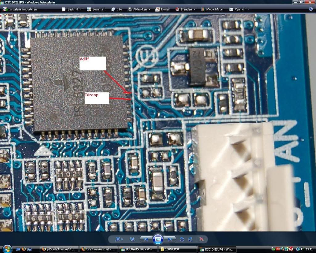 | |
|
18th July 2007, 19:02
| #6 |
| [M] Reviewer Join Date: Nov 2004 Location: Waregem
Posts: 6,466
| Hmm, indeed hard to see. Maybe another trick: the resistence between the idroop pin and the chip should be 0, right? Measure the resistence between the pin and some chips in the lower right area, you might stumble on the right chip. |
|
|
|
18th July 2007, 19:35
| #7 | |
|
Posts: n/a
| Quote:
| |
|
18th July 2007, 21:07
| #8 |
| [M] Reviewer Join Date: Nov 2004 Location: Waregem
Posts: 6,466
| This is harder then I thought it would be. In the picture you can see 3 pins identified and 3 numbers. Would you please give me the resistence between FB and the red vcore point, so I'm sure I'm on the right track. I believe that one of the two nearest numbers should give the vCore pencilmod. Please measure the resistence between the red vcore point and the four contact points of numbers 2 and 3. Number 1 should then be the vDroop mod, although I'm not sure. If so, you should again solder a VR between both contact points with the value of 500k ohm. Before you actually mod, please report back about the resistence values I requested. I wouldn't like you to kill the board because I gave wrong info 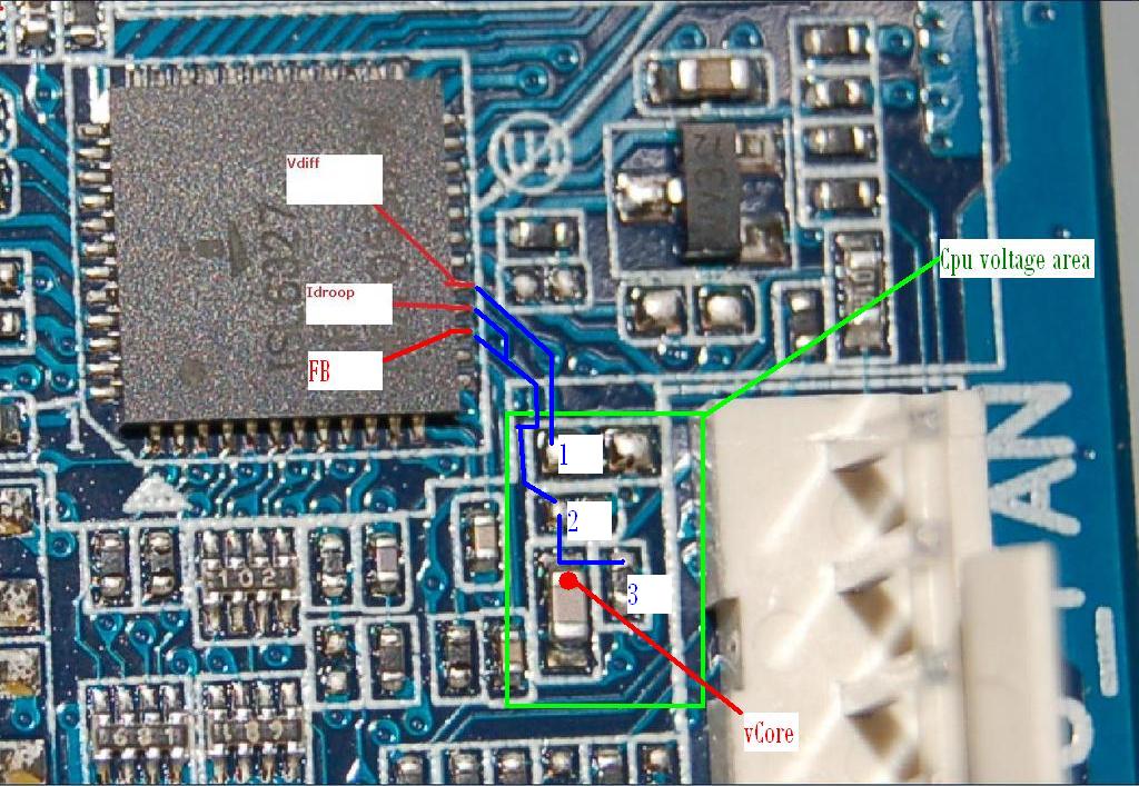 |
|
|
|
20th July 2007, 07:10
| #9 |
|
Posts: n/a
| I fully insulated my board and did the vcore yesterday. Single stage (prom modded by Jort), so i can't do the vdroop mod now. But I will measure resistance tonight on my 2'nd P35c (backup board ) |
|
20th July 2007, 08:42
| #10 |
| [M] Reviewer Join Date: Nov 2004 Location: Waregem
Posts: 6,466
| I saw the E4300 scores on HWBot |
|
|
|
 Similar Threads
 | ||||
| Thread | Thread Starter | Forum | Replies | Last Post |
| Needs GA-G33M-DS2R VDroop mod (ISL6327) | fishton | Hardware Overclocking and Case Modding | 30 | 16th September 2007 14:14 |
| Geforce go7900GS to go7900GTX BIOS Mod | jmke | WebNews | 0 | 9th November 2006 08:33 |
| Cash Box case mod | jmke | WebNews | 0 | 11th June 2006 10:52 |
| ATI Radeon To ATI FireGL Mod Guide | jmke | WebNews | 0 | 4th November 2005 00:14 |
| ATI Radeon To ATI FireGL Mod Guide Rev. 4.1 Posted! | Sidney | WebNews | 0 | 4th January 2005 02:41 |
| 6" TFT LCD Monitor Review + Two NEW 6" LCD Mod Guides | Sidney | WebNews | 0 | 6th November 2004 02:48 |
| nVidia Geforce 6800 to 6800Ultra mod | jmke | WebNews | 1 | 30th September 2004 04:27 |
| ATI Radeon To ATI FireGL Mod Guide Rev. 3.0 | jmke | WebNews | 0 | 11th August 2004 16:45 |
| ATI Radeon To ATI FireGL Mod Guide | jmke | WebNews | 2 | 19th June 2004 10:56 |
| R9600pro mod guide needed! | bizket | Hardware Overclocking and Case Modding | 17 | 26th October 2003 11:56 |
| Thread Tools | |
| |


