| geoffrey | 24th July 2007 10:51 |
Quote:
Originally Posted by Massman
(Post 149412)
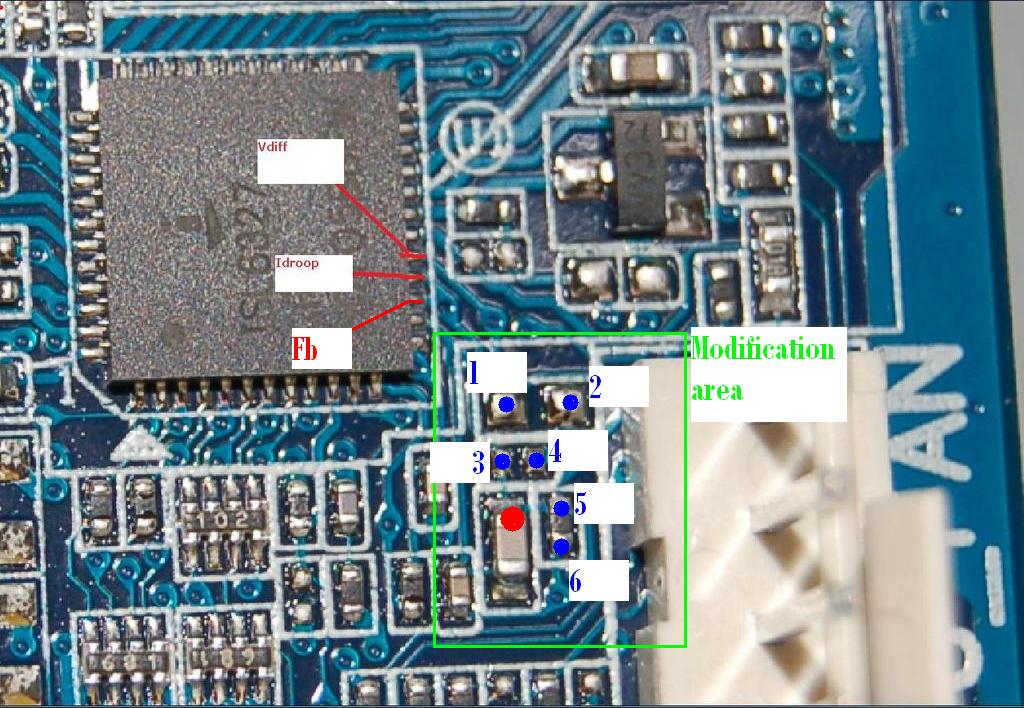
Normally, the soldering points should be the same. Follow the leads from the little chips to the power regulator on the p35-ds3 and see what leg they're attached to. Then do follow the pin from the power regulator on the p35c to the little chips and you should end up with the vdroop mod.
Before you mod, check this reasoning first by doing the same for the vcore mod!!
| Little chips are actually not called little chips, very confusing, call them SMD components instead. We have SMD resistors, capacitors, ...
@ El-snorro, try indeed to find out how the SMD components are connected to the PWM controller. Could be possible that the capacitor (on which you now soldered a VR to ground) is also used for Vdroop mod. |