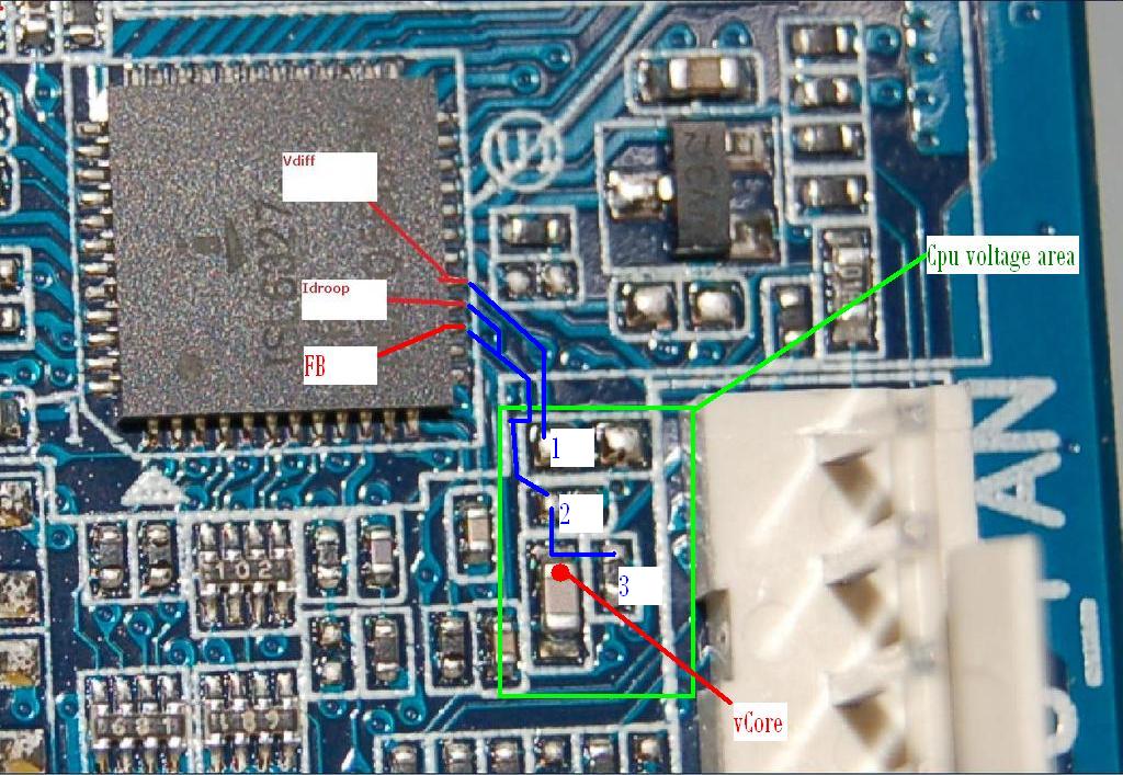
Need p35C DS3 Vcore/Vdroop mod (ISL6327) Hi everyone I am desperately searching for a vcore and vdroop mod for the p35C-DS3. The lay out is not the same as the p35-ds3r as in the guide of VR-zone.. This is from the vr-zone guide (DS3R):  And this the lay out from the P35C-Ds3:  The chip on both boards is the same, the ISL6327 This is the pin layout of the chip:  Thnx in advance! Need it really hard!:ws::ws: |
Found the vcore mod point, soldered a 50k Vr on it and the vcore mod works :D :clap: :clap: :clap:  Ni I only need the vdroop. Anyone have tips? Thnx in advance!! |
you're quick:) my vmodding days have been over for quite some time:) |
Normally, the soldering points should be the same. Follow the leads from the little chips to the power regulator on the p35-ds3 and see what leg they're attached to. Then do follow the pin from the power regulator on the p35c to the little chips and you should end up with the vdroop mod. Before you mod, check this reasoning first by doing the same for the vcore mod!! |
Quote:
I tried see where the traces go, but i cant really see it. Maybe you can see it on this hq pics (nikon d50 ftw ;) ) 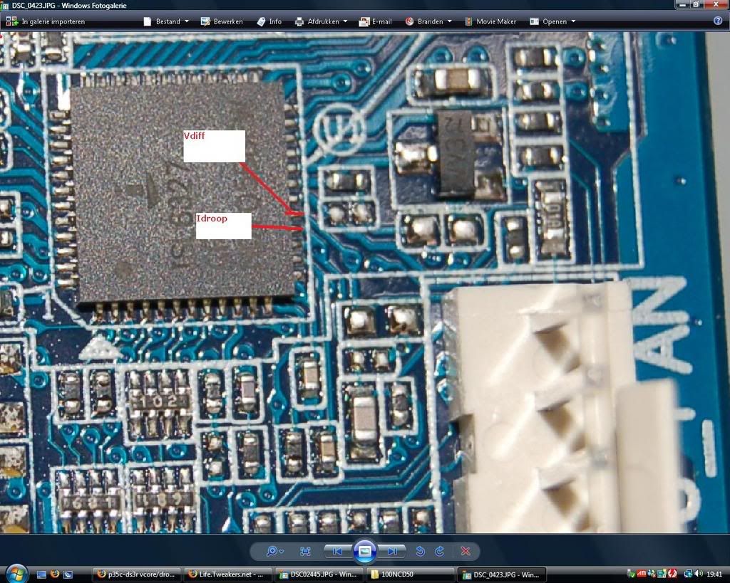 |
Hmm, indeed hard to see. Maybe another trick: the resistence between the idroop pin and the chip should be 0, right? Measure the resistence between the pin and some chips in the lower right area, you might stumble on the right chip. |
Quote:
|
I fully insulated my board and did the vcore yesterday. Single stage (prom modded by Jort), so i can't do the vdroop mod now. But I will measure resistance tonight on my 2'nd P35c (backup board ;) ) |
I saw the E4300 scores on HWBot :) |
Quote:
|
Looking good :) Will you use heavier cooling than SS? |
Quote:
|
no ln²? :( |
Quote:
Yeah post soms score's if you want, allways good to see ;-) |
Quote:
It rebooted while saving the screenshot:ws: 1,65vcore :) 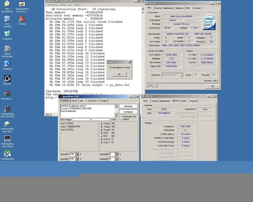 |D |
Wow ... that's the edge of stability for sure :p |
Quote:
|
That's why you need LN² instead of Dice :D |
Killer chip for shure, you should really take it the extreme tour, :) |
Snorro-bro just helped us go over 2300 points ;) WTG !! |
Quote:
|
Quote:
@ El-snorro, try indeed to find out how the SMD components are connected to the PWM controller. Could be possible that the capacitor (on which you now soldered a VR to ground) is also used for Vdroop mod. |
Quote:
|
1 Attachment(s) - Red dot is the vCore mod - Measure resistance between points 1-6 and FB/vDiff and post them here. That should give us the information we need for the vDroop mod 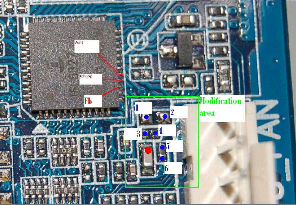 |
will measure this evening.. Kinda busy this days (crucial ballistix pc8500 coming today so hopefully i can go under 10,5s 1m on single stage :D ) |
Good luck :) |
i measure about 22.26k ohm between points 1 and 6 |
| All times are GMT +1. The time now is 14:30. |
Powered by vBulletin® - Copyright ©2000 - 2024, Jelsoft Enterprises Ltd.
Content Relevant URLs by vBSEO