Building a 300W Fan Controller from an ATX PSU What do you if you have more than 20x high speed fans in your PC and want to control them through an easy front-end? Build your own fan controller of course! In this tutorial we show you how to convert that old 300W ATX PSU into the most powerful rheobus you have seen. http://www.madshrimps.be/gotohowto.php?howtoID=77 |
1 Attachment(s) On demand, a picture which shows how the Velleman digital panel meter is configured, P3 = open, P1 = open, P2 = closed 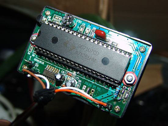 |
PMLED/5 Backside Hi there, it was me that made that request, and THANKS for helping me out, i really appreciate it. . I have tried to hook the vIN/vOUT (your brown&white) wires to have a reading, and I am unclear as to the proper way to do this. (as with a Ammeter hook up, one runs a +Positive lead to one ammeter and then back out the other ammeter lead - to your device, and that works) I have not had luck reading a steady voltage, or one that i would count as being accurate when trying to hook this LEDPM/5 Voltmeter up the same way. Am I trying this correctly? or do i got something mixed up.. *Thanks! (maybe if you could just tell me where you have your brown & white leads coming from your LEDPM/5 (vIN & vOUT) to/from your device? power? or ground? or both? ? ? Thank you for taking your time to show this. . Cheers, thenextgeek :rolleyes: |
Don't forget you have to add a resistor on the circuit, you can easily spot what I'm talking about, it is on the right side of the LCD controller Brown/white is used to read voltages on my picture. What you do is connect the two in between a potential difference. For instance you can try reading a 9V battery by connecting the VIN pin to one of the battery terminals and the VOUT pin to the other battery terminal. You can also read the supply voltage source, you can connect brown to red and white to white and read the voltage source voltage. In my PSU I connected brown with +12V (ATX: yellow) and white with ground (ATX: black). |
AhhhhhHA! I bet that's the problem, I don't have that resistor on there! :woot: hehe, sorry so newb at this, the unit i received (locally) had no manual, (or at least one that I could read;) so it has been kind of a trial and error, until now.. THANKS a lot for taking the time, I will put a resistor on as your picture indicates it should be... :ws: Cheers! thenextgeek |
1 Attachment(s) Did you just remove (desolder) the small black square part that you put that resistor to? (#RA?) I circled it in red with an arrow for referral :) Attachment 2176 Sorry I don't know the name of what that is.. I have that Resistor, but it *looks* like you removed the original part then put that resistor on? Thanks again for all your help. Cheers, thenextgeek |
1 Attachment(s) Hey, sorry if i'm cluttering your forum here, you can feel free to delete the posts if it looks bad, not a problem... :) The place you put the resistor (RA / RB) as described in the manual. . I have put the resistor on there as yours shows, but it *looks* like you may have also cut the other circuit resistor (RB? - the other one). . Is that so? I dont want to cut those little things, as i know i would NEVER be able to put it back on, way to small.. hehe ;) Ok, well thanks if you can make any suggestions, i appreciate it ! I am asking this detail, because i am getting "unstable", and usually what would appear to be "inaccurate" Voltage readings, ie; even from a fully charged 9volt batt., a DC Wall adapter (universal), etc... it dosen't seem to read, usually about 1-2 volts different, although, I can use a voltage adjuster and see the changes, they don't seem accurate enough... afaik, i also used the correct resistor, but i'm willing to double check.. but pretty sure. THANKS SO MUCH for your site, and your suggestions... Cheers, thenextgeek |
Quote:
Quote:
|
1 Attachment(s) wow, ok, somehow. . :) lucky you. ;) I talked to velleman, via email, they sent a diagram showing that RB is the one to be removed, and RA should *not* be removed (the one you have your resistor on). . and of course the resistor/s "should" be inserted into the wholes located top and bottom on there, but I often have done it differently as well. Anyways, I am seeing how to fix mine now.. heh :) I need to put the RA resistor (the little black one) back on it... *i think*, unless there's an easier way... hopefully Radio Shack has this part or something... i dunno. Any ideas? it almost *seems* that your RB resistor WAS the resistor that USE to be on RA.. #[106], because RB is [D] (or [O]), and RA on mine was [106] Jfyi?.. did you buy yours first hand/new? Mine was a new unit. Thanks, thenextgeek |
New one here too, yes I remember resoldering one of these SMD's, use tweezers, it's not that hard. |
| All times are GMT +1. The time now is 16:32. |
Powered by vBulletin® - Copyright ©2000 - 2024, Jelsoft Enterprises Ltd.
Content Relevant URLs by vBSEO