Gigabyte GA-5SMM overclocking Board layout:  66/75/83/90/95/100/105*/112*/124*/133* MHz System Bus CPU Voltage 1.3V~3.5V Clock multiplier 1.5/2.0 ...... / 5.5 CHIPSET SiS 530 & 5595 AGPset 512KB PB SRAM on board (optionally) What you should know about this board: Manual, drivers and BIOS files can be found at the Gigabyte website. No drivers needed when running WinXP SP2. Latest BIOS version F5. - No bios CPU core voltage, FSB and multiplier selection menu's. - Onboard VGA: allround slower performance, holds back overclocking as well. Can not be turned of by hardware (BIOS). - Slow CPU-NorthBridge-DRAM communication, quite a bit slower then boards based on Alladin 5 chipset + Onboard CPU core voltage, FSB and muliplier selection jumpers. + BIOS allows memory latency tweaking + 133MHz FSB support with 1/4 PCI devider + Wpcredit with correct PCR file available: software DRAM latency tweaking + CPUcool supports the ICS 9148BF-69 PLL: software FSB speed tweaking Software: BIOS, manual, drivers: http://www.gigabyte.co.nz/Support/Mo...ProductID=1579 WPCREDIT: http://www.k6plus.com/index.php?name...tails&l id=37 Sis530 PCR file for WPCREDIT: http://www.k6plus.com/index.php?name...tails&l id=40 CPUCool 8.08: http://www.majorgeeks.com/download.php?det=214 Use AWDFLASH.EXE to flash BIOS files in case you have an Award BIOS: http://support.asus.com/technicaldoc...nguage=e n-us |
My findings My findings about this board: First overclocking tests allowed me to go no higher then 112MHz front side bus resulting in 66MHz overclock on the Pentium MMX 200MHz. At this speed the system was terrible slow compared to systems running at 300MHz and Alladin 5 chipset. On Hwbot you can find 400s~440s superpi runs, at 266MHz (boot clock) my score was no better then 519s. I allready tweaked the memory latency here. 124MHz and 133MHz are no go. Later on I used a new modified PSU which offers an adjustable 3,3V line, at 3,7V I found no extra overclocking headroom. That's when I noticed VCC3 mentioned in the BIOS, it red out 3,23V. On the board I found the Infinity LX8383A IC which is a low droput 3.3V, 7.5A regulator. Modifying this part on the mobo allowed my to alter VCC3 up to 3,7V which made the mobo go up to 124MHz front side bus. At 300MHz this resulted in a superpi time of roughly 455 seconds at lowest latency's. We're getting closer ;) Next I tried up to 4V for VCC3 which made the mainboard boot at 133MHz front side bus! I tried a lower multiplier which sets the CPU speed to around 250MHz, this time I got a superpi result of 513s, I beated the previous superpi score of 519s which I made at an higher CPU speed. No software can read the FSB bus speed but it is working for sure. Unfortunately CPUCool is not working for me. EDIT: after some experiments I found at that 133MHz mode is still not going and that the board was left in 124MHz mode even though I had the correct FSB jumpers configured. You must power off the system first, a quick reboot was not enough so it seems. |
1 Attachment(s) VCC3 mod: 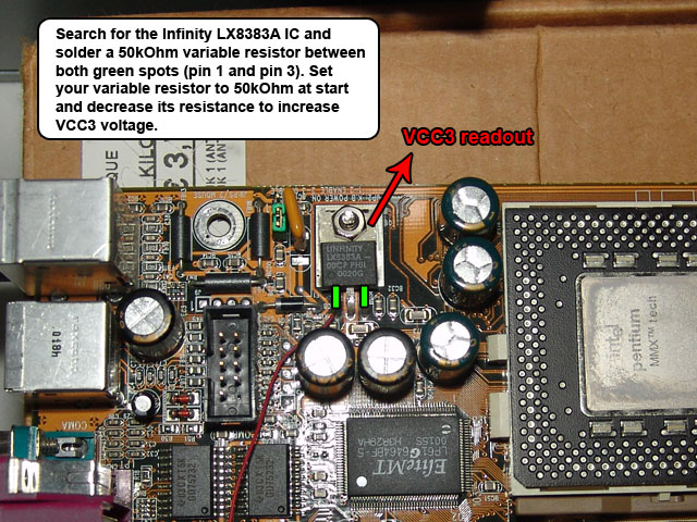 |
Some superpi results using P166 MMX and Gigabyte GA-5SMM (SIS530/512kb cache): 250MHz boot - 248MHz cpuz (124MHz*2.0) -> 8m33.819 266MHz boot - 280MHz cpuz (112MHz*2.5) -> 8m35.522 300MHz boot - 310MHz cpuz (124MHz*2.5) -> 7m34.894 Same CPU inside PCchips M590 (SIS5591/1024kb cache) 315MHz cpu -> 7m12.792 ---------- Some wprime results using P166MMX and Gigabyte GA-5SMM (SIS530/512kb cache): 300MHz boot - 310MHz cpuz (124MHz*2.5) -> 664.344s Same CPU inside PCchips M590 (SIS5591/1024kb cache) 315MHz cpu -> 657.708s Tried booting the board at 336MHz (112*3) but no go, I need to modify the CPU vcore first. EDIT: onboard you'll find the Fairchild RC5051 regulator, unfortunately it reads the direct Vcore and compares it with VID code, you can only add roughly 0,1V before the regulator shuts itself down because of an overvoltage event. I need to come up with some else. |
1 Attachment(s) More testing occurred, I found out that VCC3 is used for both the North Bridge and TAGRAM chip. My mainboard comes with "SDT sb61l256bs-8" tag ram, other static RAM of the same age is pin compatible and in a random datasheet I found the pinout of the chips, this way I can confirm that the TAGRAM chip is using VCC3 on my board. 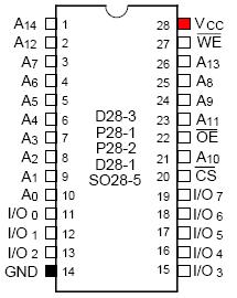 EDIT: Other TAGRAM found on Pcchips board: UT61256JC-8 has a likewise pinout (datasheet: http://www.datasheetcatalog.org/data.../190062_1.pdf). The -8 at the end of name stands for the access time being 8ns -> 125MHz. The chip itself is static RAM organized as 32K words by 8 bits, 32Kx8 TAGRAM -> supports 1MB cache on that board -> 128Mb cacheable RAM. EDIT: One can enable/disable the sis530 onboard video controller via pin MD62. Set this pin to "1" via a pull-up resistor to disable it, vice versa will enable it. EDIT: Since the LX8383A allows maximum up to roughly 4,1V when +5V line is within normal boundary's, I came up with the idea to replace it. Desoldered the LX8383A and added an external circuit based on a 5A switching power regulator. This unit allows up to 11,5V, I'm not that crazy so I went up to 4,5V maximum but I did not found the board to become more stable at 133MHz mode. I also had a quick run with a K6/2 500 which I could easily overclock up to 615MHz air cooled. It ran through superpi stable at 3V but the time was really terrible, nearly doable as slow as compared to competitors on hwbot. What's going on here? :no: |
Quote:
EDIT: WPCREDIT table by DonPedro @ K6+forums: ========================================= 50: bit 6 set to 1 (mem single write cycle) or 0 in w2k 52: bit 7 set to 0 (dram time delay set to 0) 52: bit 6 set to 1 (single read allocation) 52: bit 4 set to 1 (sync cpu-dram mode) 55: bit 2 set to 0 (disable res bit for data read dram) 56: bit 7..6 set to 11 (6 clocks) 58: bit 7..6 set to 00 (2 clocks) 58: bit 5..4 setting from 01 to 00 crashes (from 3 clocks to 2 clocks) !!!! never succeeded once here 5D: bit 4 set to 1 (dram write retire rate = x-1-1-1) 5D: bit 3 set to 0 (cas latency = 2 clocks) =========================================== |
1 Attachment(s) Closing in... 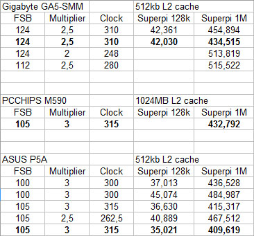 Clock for clock the P5A is very fast, compared to the PCCHIPS M590 it has only half of its cache and I still managed to beat it. Aladdin 5 chipset :ws: Downside is that I'm stuck at FSB 105 with this board, I'm curious what results I would get when using 120*2,5 (300 MHz). I was also able to match the performance of the GA5-SMM with that of the M590, which is nice considering the fact that the Sis 530 is one of the slower chipsets, and it has half amount of L2 cache too. A lot of software tweaking this time, sometimes you get awefull result and then without reason you get a fast superpi run. Maxmem tweak helped a lot. Time to crack up the CPU clock and get the gold, I'm done trying to get the 133MHz boot working. |
1 Attachment(s) Thermalright HR-03 plus & 170W TEC: 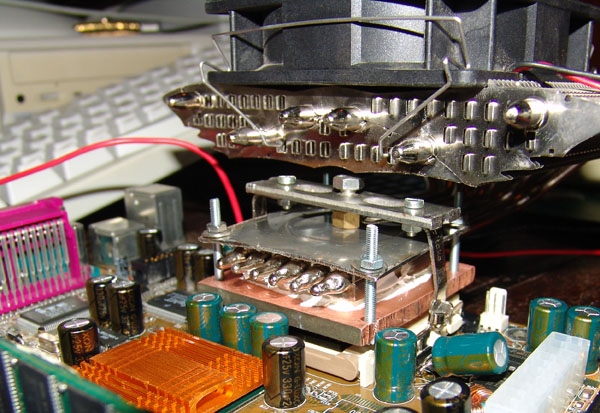 @ 12V the cold side is iced up, though when I push the CPU to the limit the ice melts. I can get sub ambient temps @5V too, when I back down the cpu speed I can let the system run for several minutes without overheating, passively cooled that is. 5V TEC + 5V fan is enough to create thermal equilibrium in which I do not get any wet on the cold side, unless of course the CPU goes idle. HR-0 plus performs good but I'm thinking about modifying one of my waterblocks so that it fits on this gigabyte mainboard. TEC cooling helped to increase system stability up to (112x3) 336MHz for the P166MMX, system initialises at (100x3,5) 350MHz but not stable enough to get through windows boot. New goal would be to get 124x3) 372MHz stable but I recon that is very hard to do without exhautic phase change cooling. I need the high FSB speed despiratly as it is the only way to the beat the competition. |
gogogogog geoffrey !!!!! |
1 Attachment(s) Prometeia mounted! |D 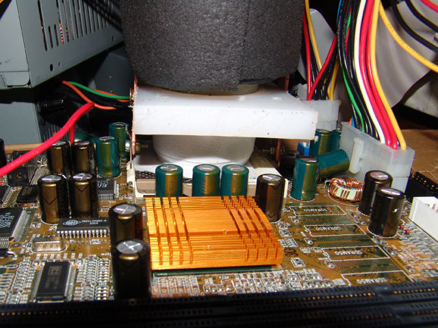 350MHz is no go, CPU needs liquid nitrogen. |
| All times are GMT +1. The time now is 09:42. |
Powered by vBulletin® - Copyright ©2000 - 2024, Jelsoft Enterprises Ltd.
Content Relevant URLs by vBSEO