
 LH Ati 9550 voltage modification
|
LH Ati 9550 voltage modification
| |||||||||
 |
 |
| | Thread Tools |
 14th May 2009, 22:19
| #1 |
| [M] Reviewer Join Date: Nov 2004 Location: Waregem
Posts: 6,466
 | Hey guys, Just trying to figure out the vmod modification of LH's 9550 card. Currently still working on it, but I need a place where I can leave my findinds  Vgpu = 1.19v - 1.20v Vmem = 2.6v Datasheet memory chips: http://www.elixir-memory.com/product....1-Jun2905.pdf. Most important information is located at page 52: Max voltage = 3.6v
__________________  |

|
|
14th May 2009, 22:27
| #2 |
| [M] Reviewer Join Date: Nov 2004 Location: Waregem
Posts: 6,466
|  Tracing back the Vmem readouts leads me back to this pin (green). Resistance is 70,8 Ohm, so I guess a 10k Ohm VR should be just fine to begin with while checking if the modification works.
__________________ |
|
|
|
14th May 2009, 22:40
| #3 |
| [M] Reviewer Join Date: Nov 2004 Location: Waregem
Posts: 6,466
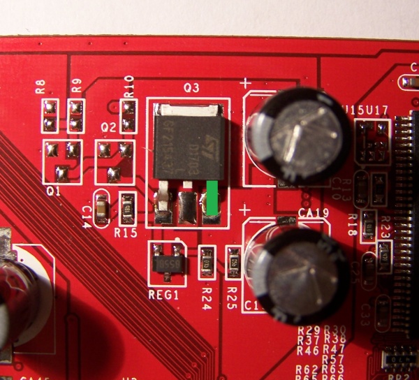
| The Vgpu read-outs can be traced back to this APM7131 chip, but I'm quite sure this isn't the Vgpu regulator. http://pdf1.alldatasheet.com/datashe...C/APM7313.html Read-out trace me back to both D1 and S2 pins. Geoffrey, what does this chip do exactly? And can it help me to find the Vgpu modification?
__________________ |
|
|
|
14th May 2009, 22:49
| #4 |
| [M] Reviewer Join Date: Nov 2004 Location: Waregem
Posts: 6,466
| Vgpu read-out leads me to this: 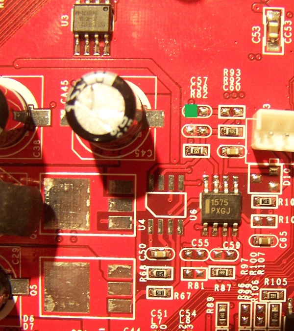 I've checked the nearby chip, but none of the pins matches the voltage measurement point, sadly enough. //EDIT: 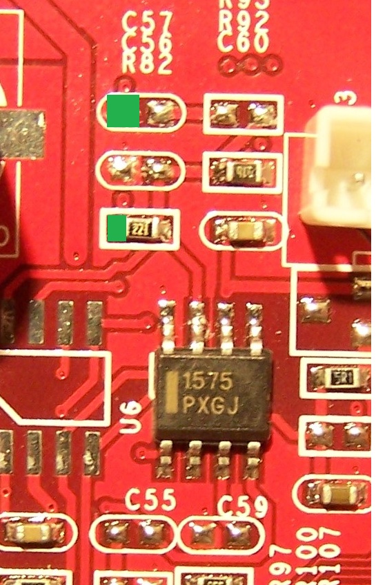
__________________ Last edited by Massman : 14th May 2009 at 22:51. |
|
|
|
14th May 2009, 22:59
| #5 |
| [M] Reviewer Join Date: Nov 2004 Location: Waregem
Posts: 6,466
| So, in between the the Vgpu regulator (chip near readout) and the actual voltage there seems to be a resistor, marked with the numbers 221. As far as I can understand, this resistor changes the voltage of pin2 (chip) from 0.98v to the 1.19v for the Vgpu. In theory, I guess I'd just have to removed that resistor and place a VR instead. Geoffrey, is it possible to add a VR somewhere so that I don't have to remove the resistor?
__________________ |
|
|
|
16th May 2009, 09:31
| #6 |
|
Posts: n/a
| If you put VR between pin2 and resistor, will the resistor survive the increase? Logicly i would put it just after the resistor? Wild guess here |
|
16th May 2009, 17:02
| #7 |
| [M] Reviewer Join Date: Nov 2004 Location: Waregem
Posts: 6,466
| Replacing the VR is actually the most correct solution, but definitly not the easiest one. It's in fact pretty simple: CHIP -> Resistor -> Vgpu, whereas normally it's just CHIP -> Vgpu In this case, I need to lower resistence to increase voltage. How I decrease resistence is not important, so in this case I can just do: PIN2 -> VR -> GND This will alter the resistence input on the resistor between chip and gpu and thus alter the Vgpu. Since the resistence on Pin2 = ~190ohm, a 10k ohm VR should do the trick. Tested and works. Just need to change the 50k ohm VR with a 10k one. Next up: the Vmem.
__________________ |
|
|
|
16th May 2009, 17:18
| #8 |
| [M] Reviewer Join Date: Dec 2008
Posts: 3,209
  | wait to fire her up, till I have some serious cooling for it... |
|
|
|
22nd May 2009, 19:33
| #9 | |
| [M] Reviewer  Join Date: Nov 2004
Posts: 4,127
| Quote:
Sorry, must have looked over this one. APM7313 : Dual N-Channel Enhancement Mode MOSFET Two MOSFET's in one chip. Source of the one MOSFET is probable connected to the drain of the other, their gate is connected to a VRM. Nothing to modify there. For Vmem you'll probable have to check with the microchip called REG1 on the PCB, and the two resistors right next to it. VMEM can be measured on one of the bigger caps at the right side of that picture. | |
|
|
|
| Thread Tools | |
| |


